Electrical enclosure accessories
for SZE2 and SZE3
From interior fittings to air conditioning: the accessory range for the baying enclosures SZE2 (welded) and SZE3 (bolted) – sorted by task, with specifications, catalogue numbers and dimensional drawings from the ZPAS catalogue.
Request a quote Configure electrical enclosure
Accessories by task: fit out, install, equip
SZE2 and SZE3 share many accessories – cable clamps, plinth corners, meter tray, power distribution panel and the 19″ profile rails have the same catalogue number. Almost everything that sits directly on the frame is specific to the series, however: mounting rails, doors, side panels, roofs and swing frames. The reason is the construction – the SZE2 is welded, the SZE3 is bolted and perforated on two planes on a 25 mm grid. Each group therefore gives the catalogue pages for both series.
The accessories can be put together in the electrical enclosure configurator; panel building delivers the enclosure fitted and wired.
Mounting system & mounting plate
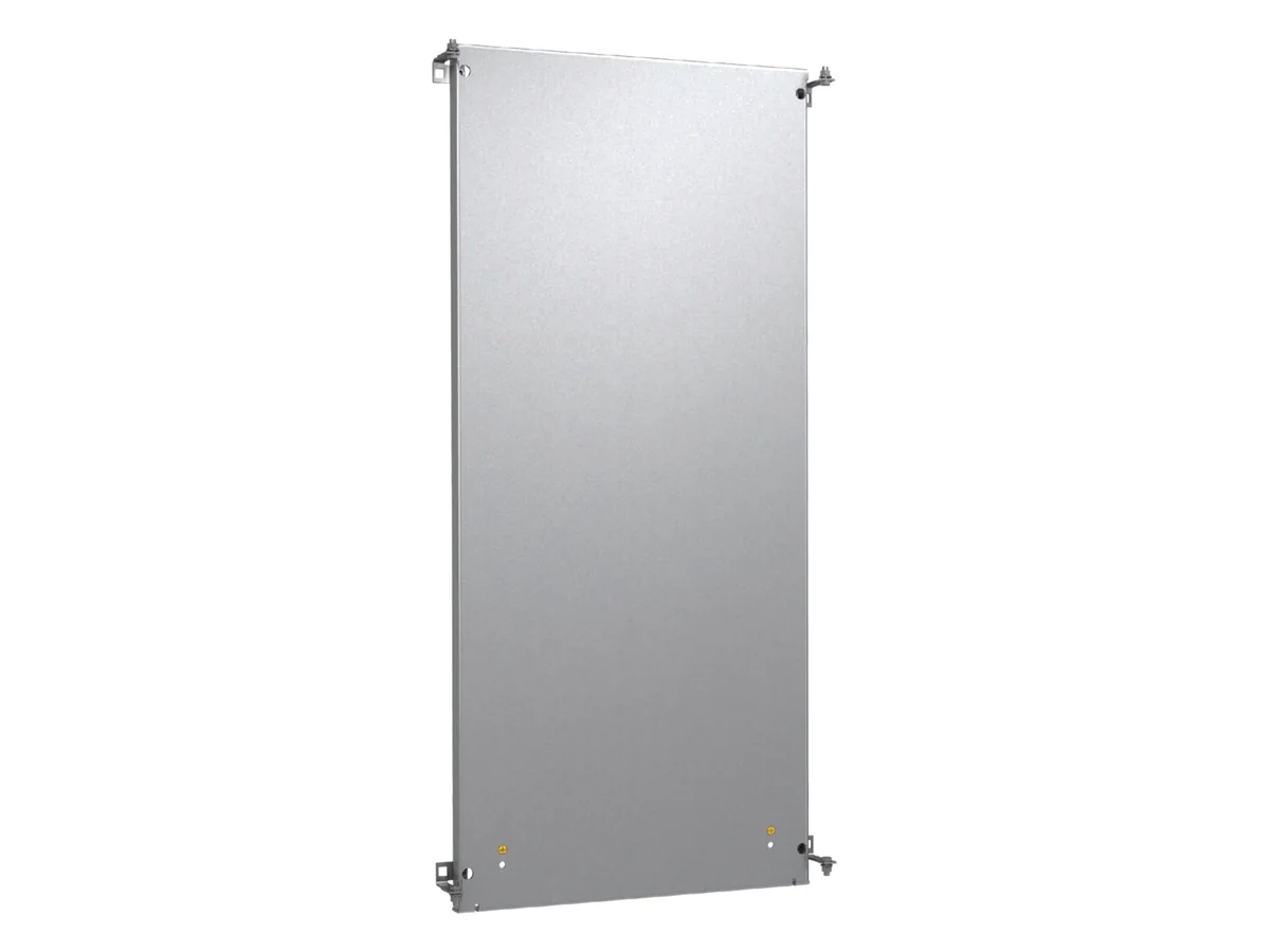
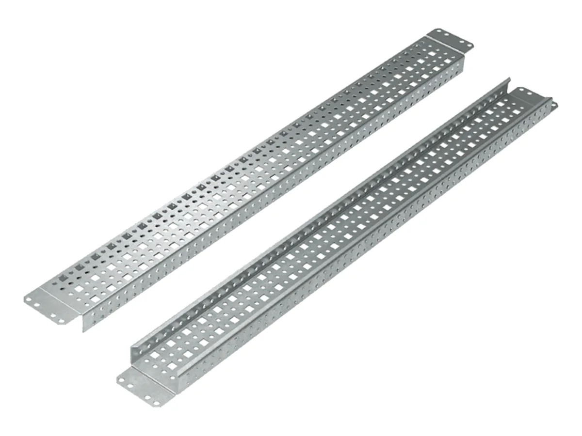
The mounting plate made of 3 mm galvanised sheet steel is included in the scope of delivery for SZE2 and SZE3. Accessories include guides that make insertion easier and, for the SZE3, supports for mounting between the rear frame profiles and the mounting plate connector for a continuous level along the row of enclosures. Anyone who needs more than one level builds with rails: with the CLASSIC and UNI systems on the SZE2, with mounting rails A and B on the SZE3. For distribution boards with modular devices there is the ZPAS module system for the SZE2.
For the SZE2 the catalogue gives a load capacity of 1,000 kg on the mounting plate and 1,600 kg on the mounting rail frame.
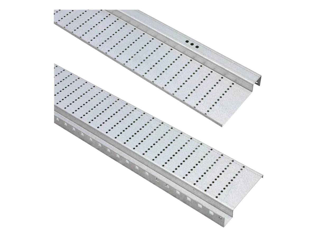 DETAILSEITE · MIT KATALOGNUMMERNMounting system for electrical enclosuresMounting plate with guides and supports, CLASSIC and UNI, mounting rails A, B and C, fixing accessories, profile rails II, TS 35 DIN rail, module system and equipment shelves – all lengths and versions in tables.To the mounting system →
19″ equipment in the enclosure
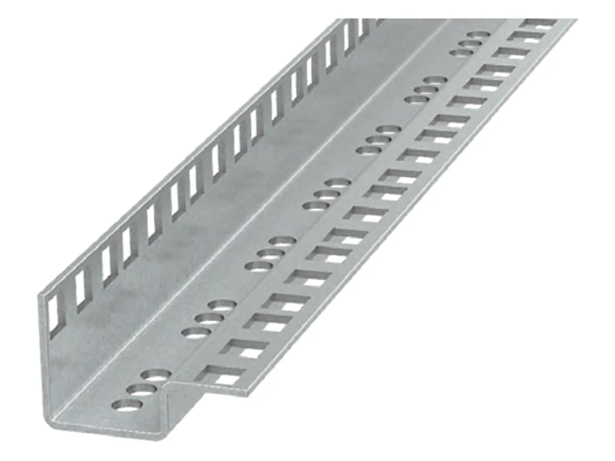
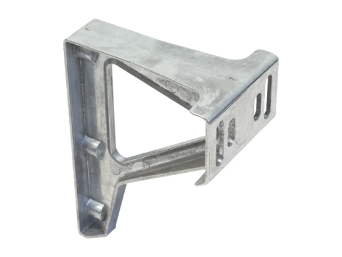
There are two ways to fit 19″ equipment in the enclosure. The 19″ swing frame swings out to the front (max. 120°) and makes the rear of the equipment accessible: with door stop, two swing handles with double-bit insert and left- or right-hand hinge by turning through 180°, load capacity 150 kg. The fixed 19″ frame made of profile rails (24 to 47 U) sits on UNI mounting rails in the SZE2 and on mounting rails C in the SZE3; in 800 mm wide enclosures offset brackets create the 19″ dimension. For 1000 and 1200 mm wide SZE2 an individual frame is built from UNI mounting rails.
- SZE2: swing frames for 600 and 800 mm width, symmetrical (central) or – at 800 mm – asymmetrical (to the side) with up to 440 mm installation depth; RAL 7035. On request with 180° opening angle.
- SZE2 with 200 kg: ZPAS builds a swing frame with increased load capacity on request – then with support roller and a specially reinforced enclosure frame that does not deform when opened under load.
- SZE3: swing frame for 800 mm width, galvanised, up to 350 mm installation depth.
The enclosure with swing frame should be fixed to the floor so that it cannot tip.
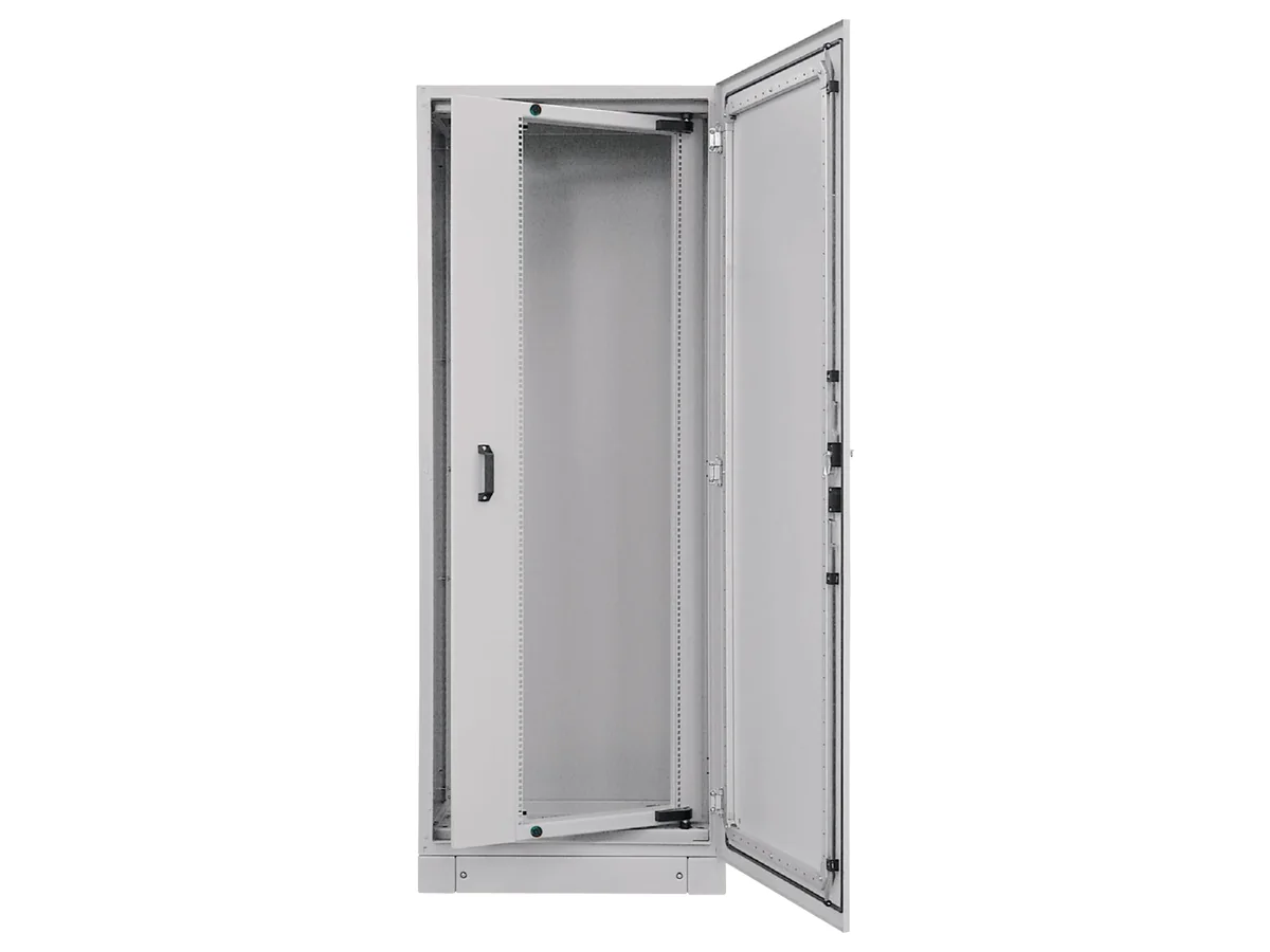
19″ swing frame
| Series | Width | Height | Rack units | Version | Max. installation depth | Catalogue number |
|---|---|---|---|---|---|---|
| SZE2 | 600 mm | 2000 mm | 40 U | symmetrical | 180 mm | W-1951-29-05-011 |
| SZE2 | 600 mm | 2200 mm | 44 U | symmetrical | 180 mm | W-1951-29-06-011 |
| SZE2 | 800 mm | 2000 mm | 40 U | symmetrical | 360 mm | W-1951-29-01-011 |
| SZE2 | 800 mm | 2000 mm | 40 U | asymmetrical | 440 mm | W-1951-20-01-011 |
| SZE2 | 800 mm | 2200 mm | 44 U | symmetrical | 360 mm | W-4950-26-00-011 |
| SZE2 | 800 mm | 2200 mm | 44 U | asymmetrical | 440 mm | W-4950-27-00-011 |
| SZE3 | 800 mm | 2000 mm | 40 U | – | 350 mm | W-6282-63-02-C08 |
| SZE3 | 800 mm | 2200 mm | 44 U | – | 350 mm | W-6282-63-01-C08 |
Load capacity 150 kg, opening angle max. 120°, 1 U = 44.45 mm; supplied with fixing accessories, packaging 1 pc.
19″ frame: profile rails, offset brackets, cross members
| Length | Rack units | Catalogue number | Length | Rack units | Catalogue number |
|---|---|---|---|---|---|
| 1067 mm | 24 U | W-1718-97-08-000 | 1600 mm | 36 U | W-1718-97-05-000 |
| 1200 mm | 27 U | W-1718-97-16-000 | 1689 mm | 38 U | W-1718-97-04-000 |
| 1245 mm | 28 U | W-1718-97-07-000 | 1734 mm | 39 U | W-1718-97-13-000 |
| 1334 mm | 30 U | W-1718-97-15-000 | 1778 mm | 40 U | W-1718-97-03-000 |
| 1422 mm | 32 U | W-1718-97-06-000 | 1867 mm | 42 U | W-1718-97-02-000 |
| 1467 mm | 33 U | W-1718-97-14-000 | 2089 mm | 47 U | W-1718-97-20-000 |
| Component | Specifications | Catalogue number |
|---|---|---|
| Offset brackets | Die-cast zamak, for 800 mm wide SZE2 and SZE3, with fixing accessories | W-5205-90-00-C12 |
| 19″ cross member | for equipment on the 19″ profile rails or on the swing frame, galvanised, without fixing accessories (W-1951-44-02-000) | W-6414-05-00-000 |
| Mounting kit for profile rails | fixes a pair of 19″ profile rails to UNI mounting rails | W-SB00-37-04-000 |
19″ profile rails, offset brackets and cross members are identical for SZE2 and SZE3; profile rails made of galvanised sheet steel, without fixing accessories, packaging 1 pc. UNI mounting rails (SZE2) and C (SZE3) are described under mounting system.
Plinth, castors & transport
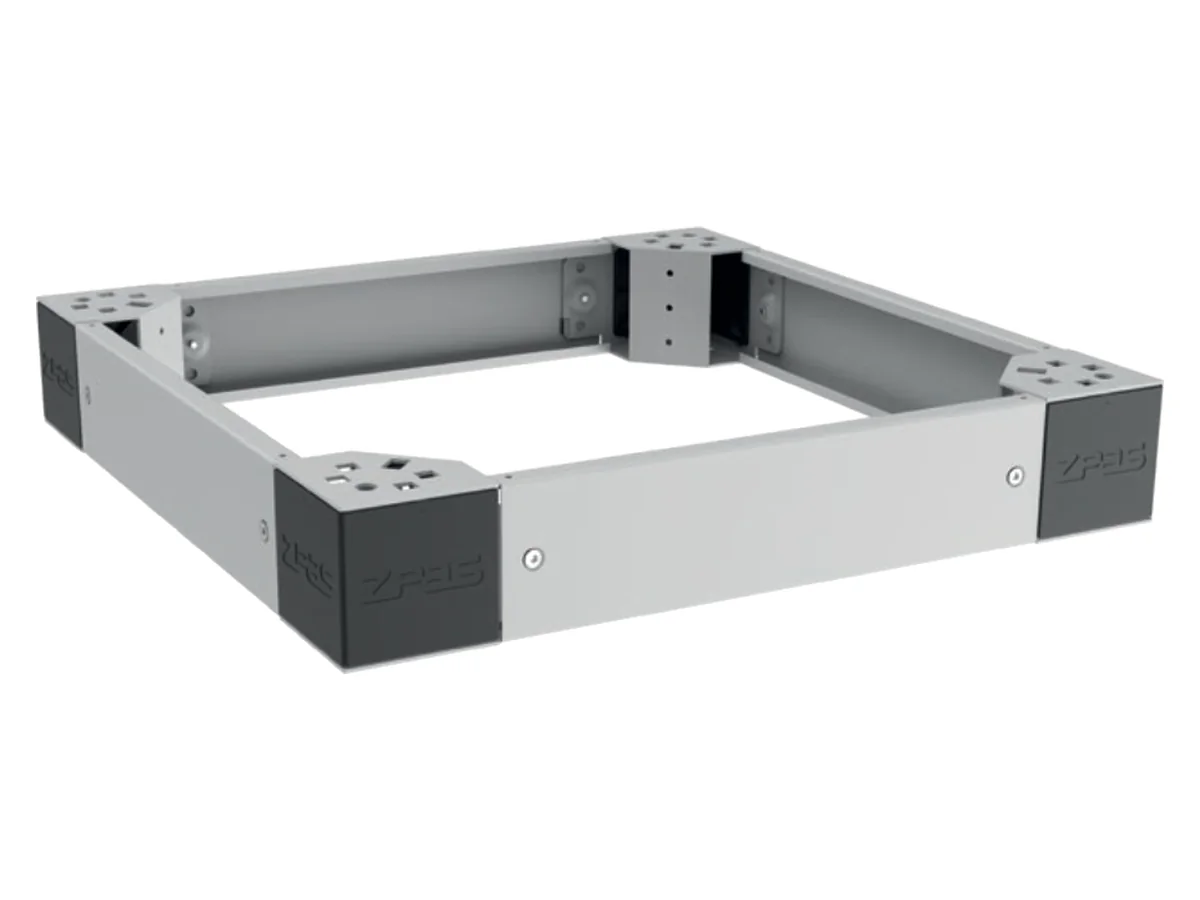
Two plinth designs: the welded plinth is intended for high loads and for enclosures that are moved by forklift without a pallet – 100 or 200 mm high on the SZE2, 100 mm on the SZE3. The bolted plinth consists of four plinth corners that carry the entire enclosure weight and removable panels – solid, perforated or with brush strip for cable entry. The panels can also be removed from a loaded enclosure; the corners take a levelling set (0–10 mm) or vibration dampers (10 mm rubber). Plinths can be connected in a row and in height, maximum 4 × 100 mm.
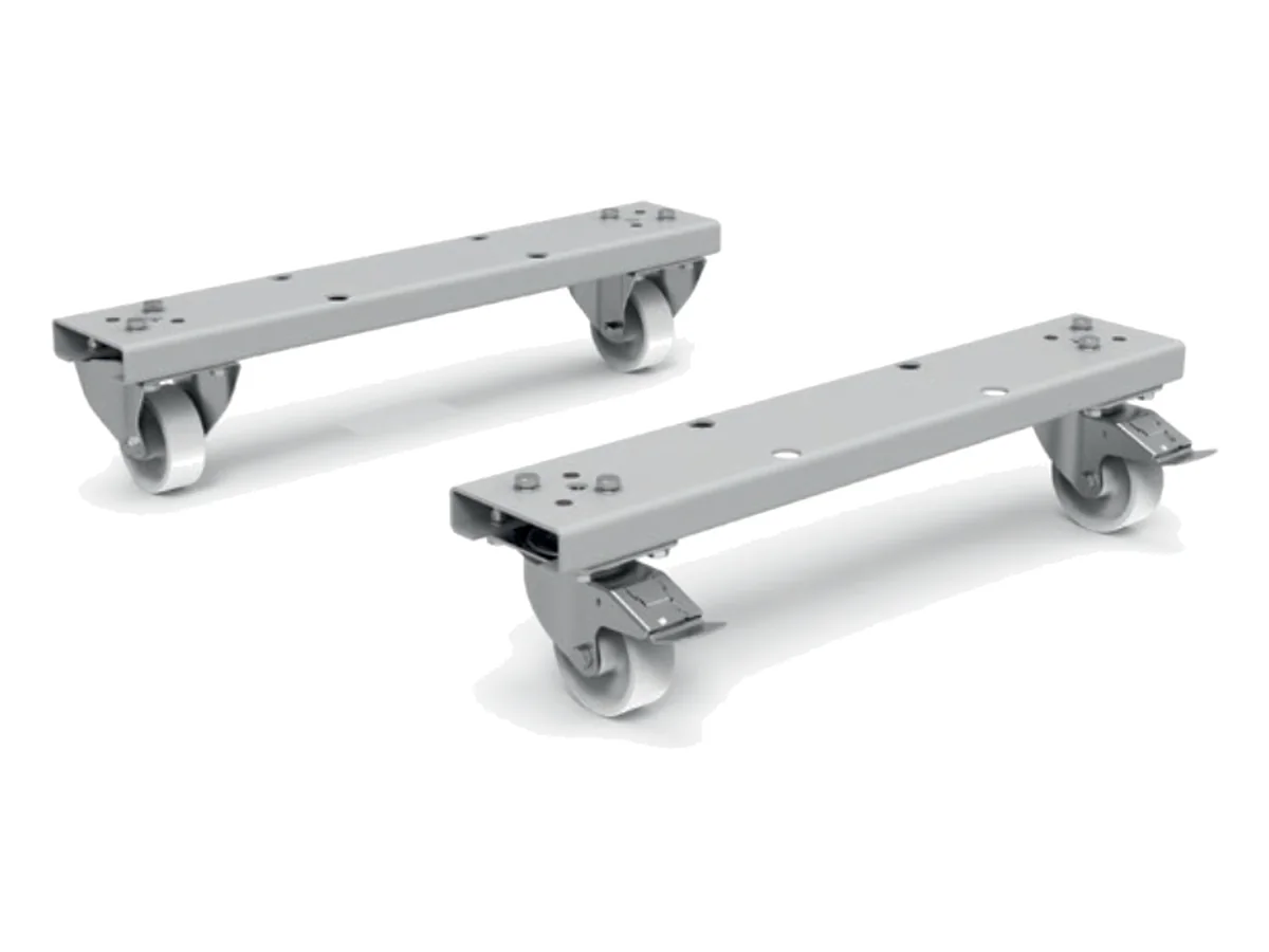
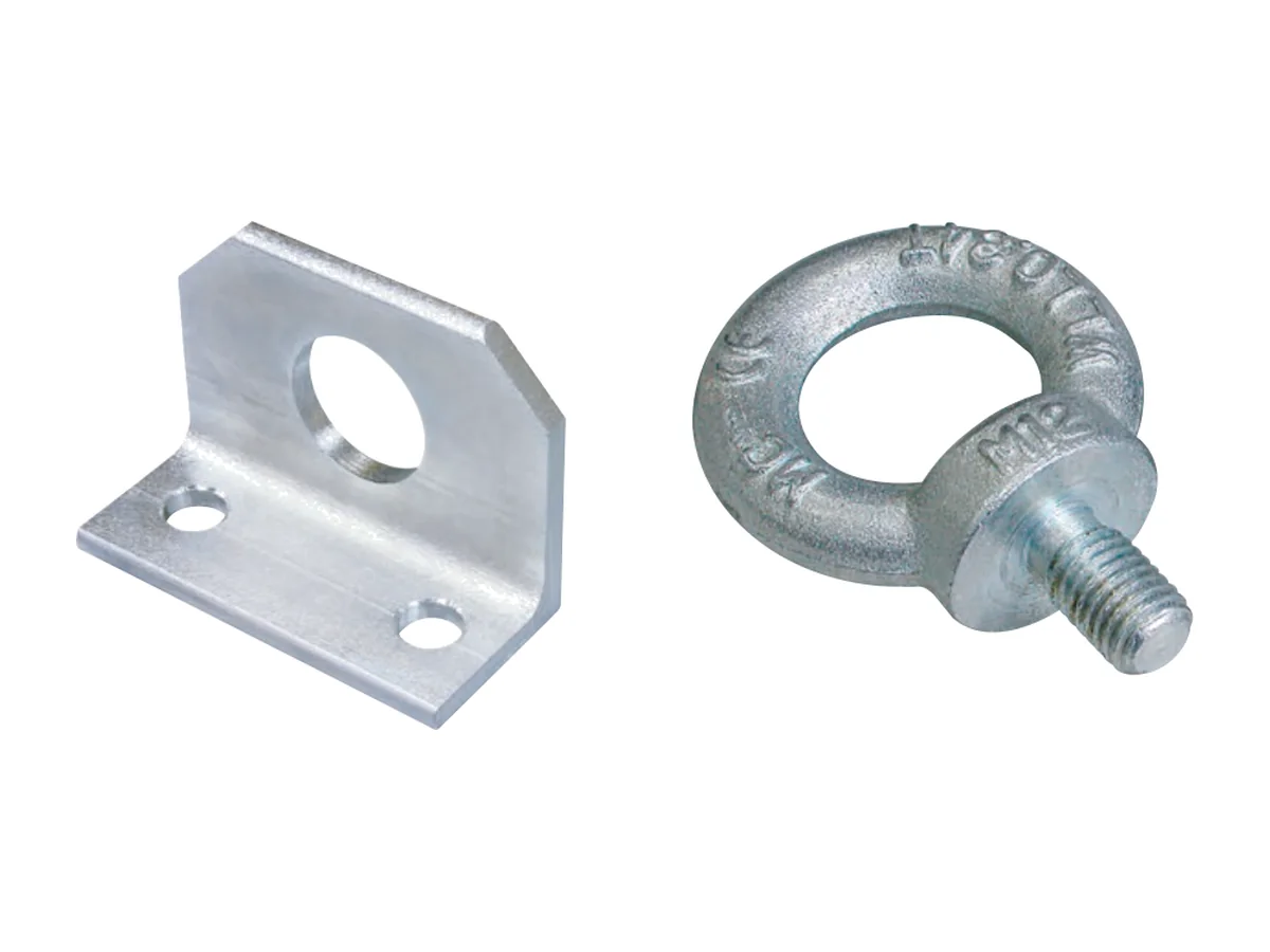
For the SZE2 (and SZE2 PC) in 600, 800 or 1000 mm width there is a castor set made of castors type 300 and support rails: load capacity 600 kg, height 135.5 mm. Lifting eyes are available single (eye opening 30 mm, thread M12) and double (opening 38 mm, two holes for M12 screws from the enclosure scope of delivery). According to the catalogue, an individually lifted enclosure on four eyes at a 60° rope angle may weigh max. 550 kg, with vertical pull max. 900 kg; larger groups of enclosures are better transported on a common welded plinth.
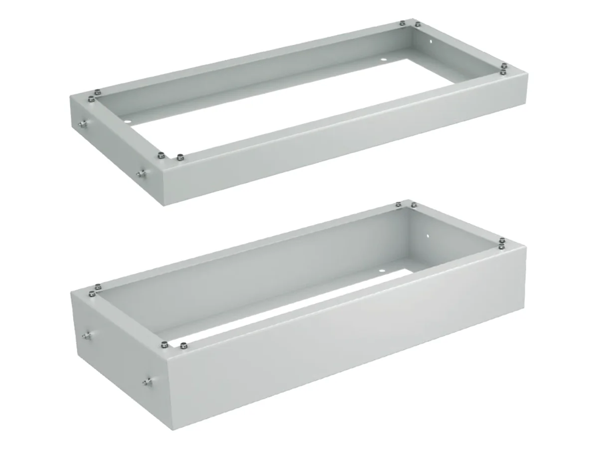
| Component | Specifications | SZE2 | SZE3 |
|---|---|---|---|
| Welded plinth 100 mm | RAL 7035, with fixing accessories | all sizes → | all sizes → |
| Welded plinth 200 mm | RAL 7035, with fixing accessories | all sizes → | – |
| Plinth corners (set of 4) | 100 mm high, removable plastic covers | W-6935-74-00-011 | W-6935-74-00-011 |
| Plinth panels | solid, perforated or with brush strip | all sizes → | all sizes → |
| Levelling set (4 screws) | Adjustment range 0–10 mm | W-6935-Z1-02-000 | W-6935-Z1-01-000 |
| Vibration dampers (set of 4) | 10 mm rubber; fix plinth to the floor | W-M1Z-00-0048-000-4 | W-M1Z-00-0048-000-4 |
| Plinth connection kit | In a row or in height, max. 4 × 100 mm | W-6935-Z1-03-000 | W-6935-Z1-03-000 |
| Castor type 300 with brake (2 pcs) | for castor set SZE2 | W-SB73-00-01-000-2 | – |
| Castor type 300 without brake (2 pcs) | for castor set SZE2 | W-SB73-00-02-000-2 | – |
| Support rails (2 pcs) | for enclosure width 600 / 800 / 1000 mm | 600: W-SB74-00-01-011-2800: W-SB74-00-02-011-21000: W-SB74-00-03-011-2 | – |
| Lifting eye, single | Eye opening 30 mm, thread M12 | M1F-00-0106 | M1F-00-0106 |
| Lifting eye, double | Opening 38 mm, 2 holes for M12 | W-1951-68-00-000 | W-6282-69-00-C12 |
Castor set: per enclosure two castors with and two without brake plus two support rails matching the enclosure width, fixing elements included in the scope of delivery. Lifting eyes are screwed into the roof plate (SZE2) or into the upper corners of the enclosure frame (SZE3). Welded plinths and plinth panels in all sizes as well as the lifting load capacities are on the page Doors, panels, roof & plinth.
Doors, panels, roof & baying
Doors: the standard on both series is the sheet steel door with double-bit lock. Accessories include glazed doors with safety glass and doors with passive ventilation, single or double. On the SZE2 they replace the front door or the rear sheet steel panel (max. 120° opening angle); according to the current catalogue, sheet steel and glazed doors have IP 54/55, ventilated doors IP 54. On the SZE3 the door can be mounted at the front, rear or side thanks to the symmetrical frame; the 4-point lock is outside the sealing area, the opening angle is up to 150°. Sheet steel and glazed door SZE3: IP 55, with passive ventilation IP 54.
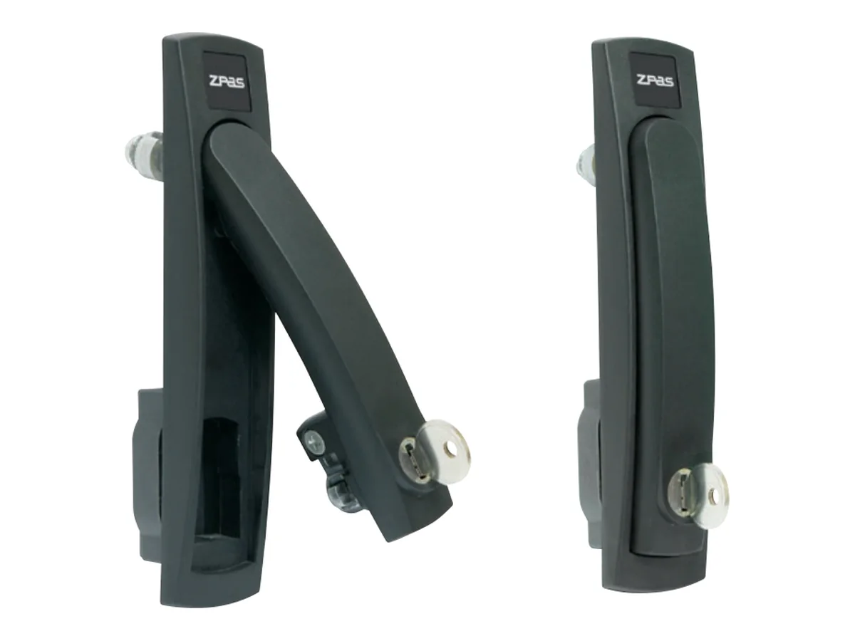
Locking: instead of the double-bit lock there is a swing handle with profile half-cylinder – on the SZE2 handle and half-cylinder are ordered separately, on the SZE3 the handle comes complete with profile half-cylinder or double-bit insert. The door stay holds the open door and protects the hinges (on the SZE2 not for glazed doors).
Side panels and roof: SZE2 side panels are available flush (within the enclosure width, in a row also usable as a partition) or protruding (+25 mm per side), all with foamed-in PU seal and threaded studs for earthing. The full roof increases the height of the SZE2 by 41.5 mm (5 mm air gap), the perforated roof by 70 mm; on the SZE3 the roof adds 41 mm. Instead of the full top cover there is a top cover with opening (380 × 210 or 380 × 380 mm) for the SZE3, for a blanking cover or fan panel.
Roof and floor plates: blanking covers retain the degree of protection; perforated plates and plates with filter mat, brush or foam pass-through open the enclosure for air or cables – the degree of protection then drops to IP 00 to IP 21, depending on the version. Sliding floor plates with foam or brush strips form a cable pass-through with adjustable width.
Baying: the partition wall separates bayed enclosures without increasing the width. SZE2 are connected with the baying accessories (set for two enclosures, with 6 m self-adhesive seal), SZE3 with the set of enclosure frame connectors type A and B and 6 m sealing tape. The mounting plate connector creates a continuous mounting level across the enclosure boundary.
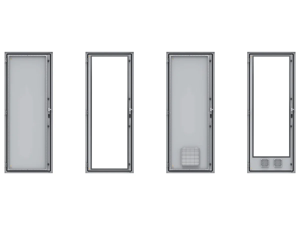
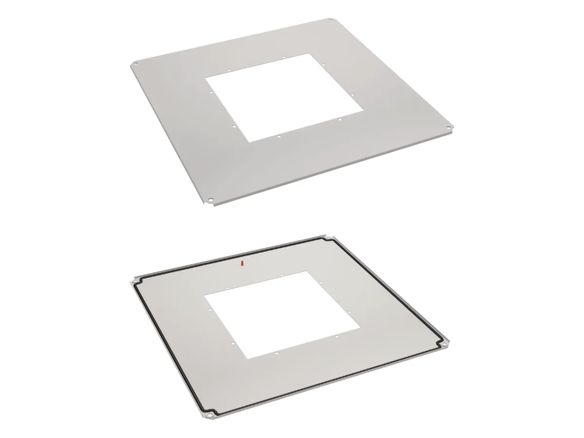
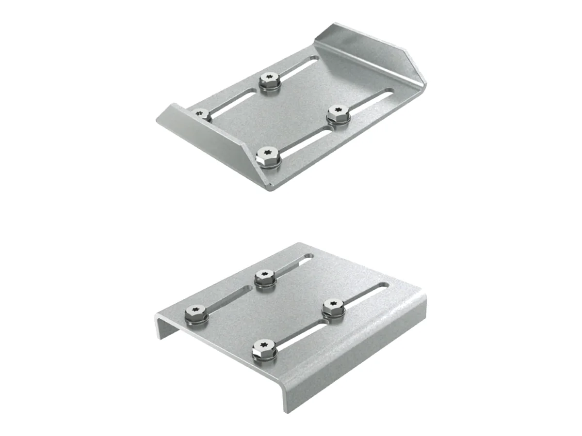 DETAILSEITE · MIT KATALOGNUMMERNAccessories: doors, panels, roof & plinthSingle and double doors, side and partition panels, roofs, top cover, roof and floor plates, baying accessories, plinths with panels, castor set and lifting eyes – every enclosure size with catalogue number.View all sizes →
| Component | SZE2 | SZE3 |
|---|---|---|
| Single doors (600/800 mm) | all sizes → | all sizes → |
| Double doors (1000/1200 mm) | all sizes → | all sizes → |
| Door stay | W-1951-32-00-000 | W-6935-17-00-000 |
| Swing handle | without cylinder: M1H-01-0024profile half-cylinder + 1 key: M1H-02-0028 | profile half-cylinder + 2 keys: M1H-00-0531double-bit + 1 key: M1H-00-0532 |
| Side panels (pair) | flush or protruding → | all sizes → |
| Full roof | two widths → | all sizes → |
| Perforated roof | 600/800 × 600/800 mm → | – |
| Top cover with opening | – | all sizes → |
| Plates and blanking covers for roof | all sizes → | all sizes → |
| Sliding floor plates | all sizes → | all sizes → |
| partition | all sizes → | all sizes → |
| Baying accessories / frame connectors | W-1951-45-00-000 | W-6678-00-00-000-EM-S |
For doors, side panels, roofs, partition walls and plates the catalogue number depends on enclosure height, width and depth – all sizes with catalogue numbers are on the page Doors, panels, roof & plinth. Plates and blanking covers for the roof or top cover and the sliding floor plates have the same catalogue numbers on SZE2 and SZE3.
Cable management, earthing & EMC
Cables are secured on cable rails with cable clamps – clamps for 8 to 56 mm cable diameter in twelve steps, 5 pieces each. The cable rail is fixed to the horizontal profiles of the enclosure frame or via cable rail brackets in the bolted plinth. On the SZE2 there is also the horizontal cable support rail, which sits on the frame profile in depth or on the door frame.
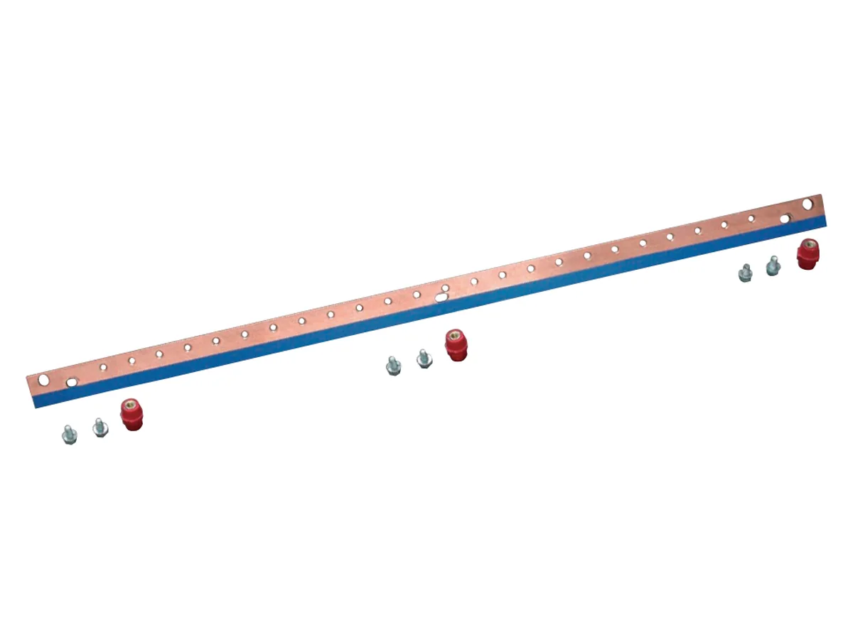
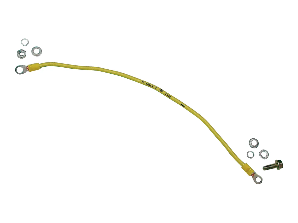
For equipotential bonding there is the earthing bar with M8 threaded holes (SZE2: set with UNI mounting rail, galvanised earthing bar 30 × 4 mm; SZE3: galvanised flat steel with holder), the copper shielding rail (SZE2: 30 × 4 mm with 3 insulators and M6 thread, without blue strip also usable as an earthing bar; SZE3: with holder, insulators and M8 thread), the earthing leads kit (9 insulated 6 mm² leads with M8 lugs) for removable enclosure parts and the vertical earthing bar for the 19″ swing frame (copper 30 × 3 mm, 1650 mm long, M5 thread). Background on shielding and equipotential bonding in the EMC guide.
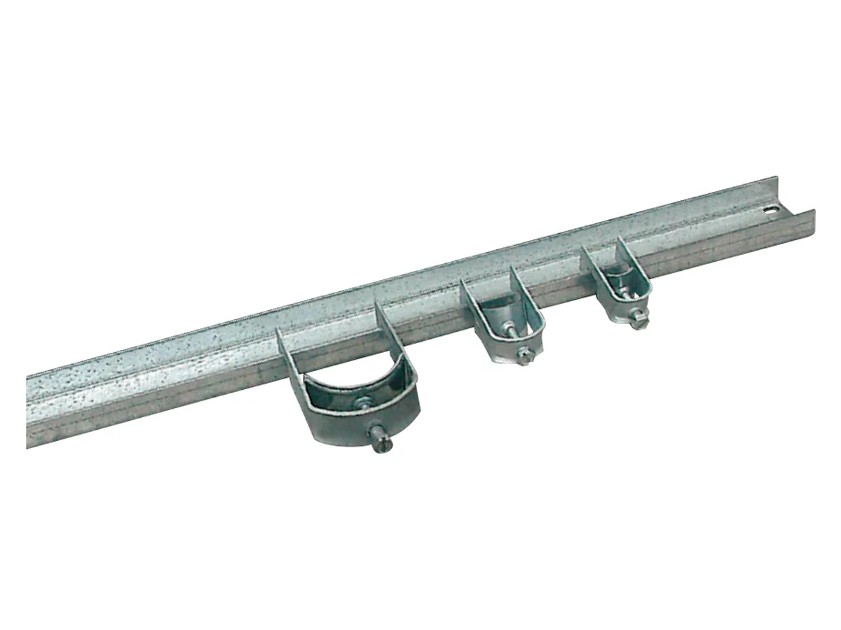
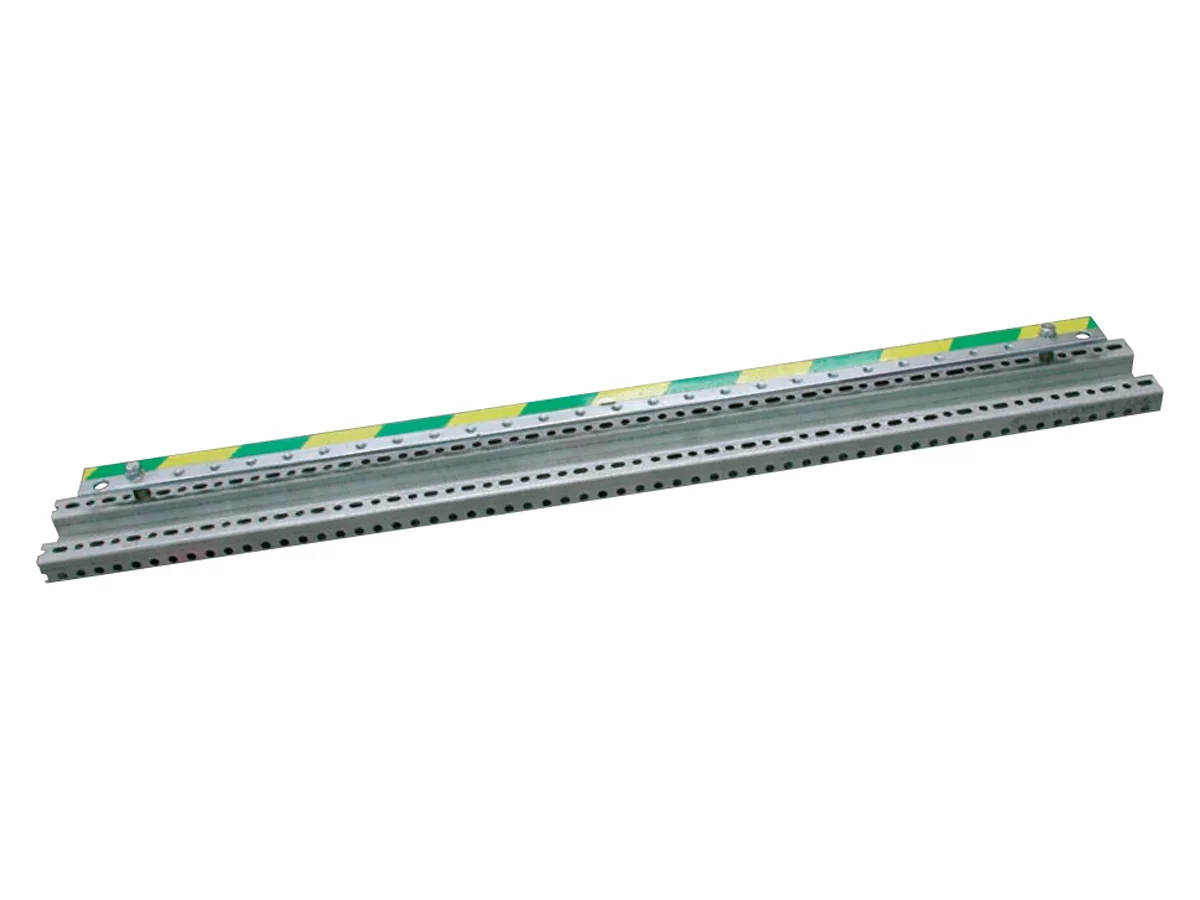
Cable clamps (5 pcs) – SZE2 and SZE3
| Cable diameter | Catalogue number | Cable diameter | Catalogue number |
|---|---|---|---|
| 8–12 mm | W-K12U-00-00-000-5 | 32–36 mm | W-K36U-00-00-000-5 |
| 12–16 mm | W-K16U-00-00-000-5 | 36–40 mm | W-K40U-00-00-000-5 |
| 16–20 mm | W-K20U-00-00-000-5 | 40–44 mm | W-K44U-00-00-000-5 |
| 20–24 mm | W-K24U-00-00-000-5 | 44–48 mm | W-K48U-00-00-000-5 |
| 24–28 mm | W-K28U-00-00-000-5 | 48–52 mm | W-K52U-00-00-000-5 |
| 28–32 mm | W-K32U-00-00-000-5 | 52–56 mm | W-K56U-00-00-000-5 |
Cable rails and earthing bars by enclosure width
| Component | Series | 600 mm | 800 mm | 1000 mm | 1200 mm |
|---|---|---|---|---|---|
| Cable rail (frame or plinth) | SZE2 | W-1951-22-04-000 | W-1951-22-03-000 | W-1951-22-02-000 | W-1951-22-01-000 |
| Cable rail in the plinth | SZE3 | W-1951-22-04-000 | W-1951-22-03-000 | W-1951-22-02-000 | W-1951-22-01-000 |
| Cable rail on the enclosure frame | SZE3 | W-6282-72-04-000 | W-6282-72-03-000 | W-6282-72-02-000 | W-6282-72-01-000 |
| Earthing bar kit | SZE2 | W-1951-24-04-000 | W-1951-24-03-000 | W-1951-24-02-000 | W-1951-24-01-000 |
| Earthing bar with holder | SZE3 | W-6282-78-01-000 | W-6282-78-02-000 | W-6282-78-03-000 | W-6282-78-04-000 |
| Shielding rail, blue strip | SZE2 | W-1951-25-04-000 | W-1951-25-03-000 | W-1951-25-02-000 | W-1951-25-01-000 |
| Shielding rail without strip | SZE2 | W-1951-25-04-000-BT | W-1951-25-03-000-BT | W-1951-25-02-000-BT | W-1951-25-01-000-BT |
| Shielding rail with holder | SZE3 | W-6282-79-04-000 | W-6282-79-03-000 | W-6282-79-02-000 | W-6282-79-01-000 |
| Component | Specifications | SZE2 | SZE3 |
|---|---|---|---|
| Earthing leads kit | 9 insulated copper leads 6 mm², lugs for M8 | W-1951-33-00-000 | W-6282-50-00-000 |
| Vertical earthing bar | for 19″ swing frame, copper 30 × 3 mm, 1650 mm, M5 | W-7580-11-00-000 | W-7580-11-00-000 |
Cable rails SZE2 558–1158 × 49 × 20 mm, without fixing accessories; order cable clamps separately. Cable rail brackets for the bolted plinth and the horizontal cable support rail (SZE2): see catalogue p. 44 and p. 89 respectively.
Electrics, metering & lighting
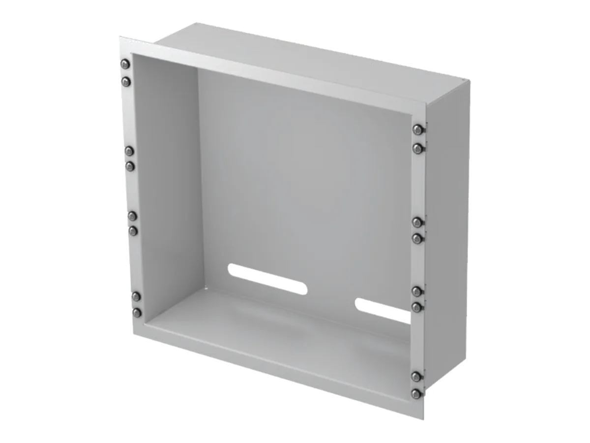
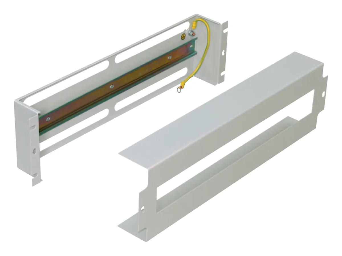
The meter tray takes electricity meters – on 19″ profile rails or the swing frame with 10 U (100 or 150 mm deep) or 8 U (150 mm deep), on profile rails II 450 mm high in 482.6 or 682.6 mm width. The power distribution panel is a 19″ panel with 3 U for up to 22 modules type S (17.5 mm), supplied empty with mounting plate, 35 mm DIN rail and housing, in RAL 7035 or RAL 9005 – fitted on request.
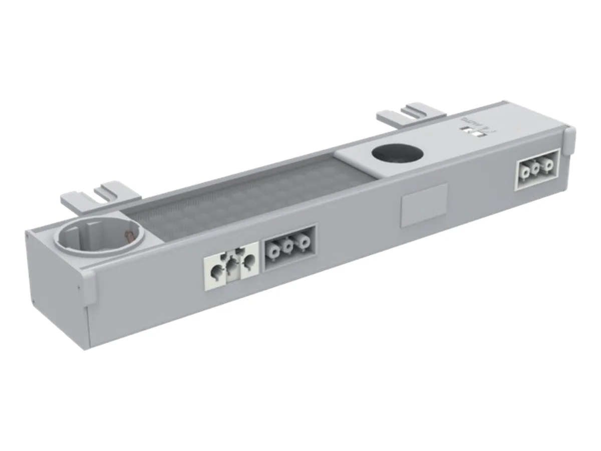
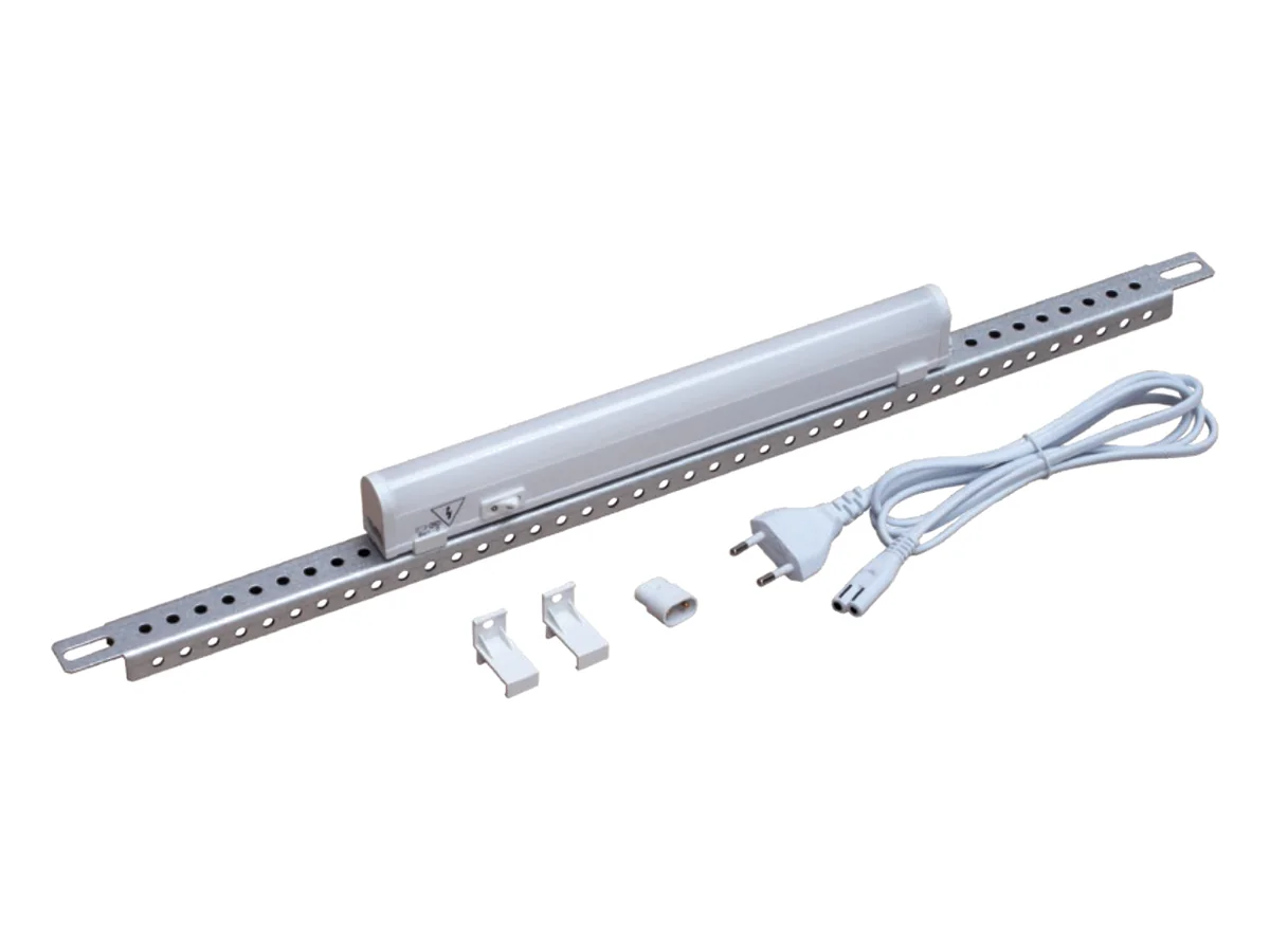
The system lighting is an LED luminaire (850 lm, 4000 K, 230 V, 8 W) with Schuko socket (max. 16 A) and 0-1-AUTO switch. It is fixed to the upper frame; adjacent luminaires are connected via system cables and can be switched by a door position switch. Simpler is the lighting set with 5 W LED luminaire, on/off switch and 1.5 m connection cable, optionally with connection cable and door position switch. The A4-size circuit diagram pocket that sticks to the door goes with it.
| Component | Specifications | SZE2 | SZE3 |
|---|---|---|---|
| Meter tray 10 U, 100 mm deep | on 19″ profile rails/swing frame, inside 402 × 440 mm | W-5716-A1-16-01-011 | W-5716-A1-16-01-011 |
| Meter tray 10 U, 150 mm deep | inside 402 × 440 mm | W-5716-38-01-011 | W-5716-38-01-011 |
| Meter tray 8 U, 150 mm deep | inside 315 × 440 mm | W-6878-78-00-011 | W-6878-78-00-011 |
| Meter tray 450 × 482.6 mm | on profile rails II, inside 407 × 440 mm, 100 / 150 mm deep | 100: W-5716-A1-16-02-011150: W-5716-38-02-011 | – |
| Meter tray 450 × 682.6 mm | on profile rails II, inside 407 × 640 mm, 100 / 150 mm deep | 100: W-5716-A1-16-03-011150: W-5716-38-03-011 | – |
| Power distribution panel | 3 U (133 mm), 482.6 mm wide, 60 mm deep, 22 modules type S | RAL 7035: W-PS3U-00-00-011RAL 9005: W-PS3U-00-00-161 | RAL 7035: W-PS3U-00-00-011RAL 9005: W-PS3U-00-00-161 |
| System lighting | LED 850 lm, 4000 K, 8 W, Schuko max. 16 A | 600: W-1951-80-04-011800: W-1951-80-03-0111000: W-1951-80-02-0111200: W-1951-80-01-011 | 600–1200: W-6282-39-02-000 |
| System cable 0.6 m | for enclosure width 600–800 mm | M1T-02-0012 | M1T-02-0012 |
| System cable 1.0 m | for enclosure width 1000–1200 mm | M1T-02-0011 | M1T-02-0011 |
| Connection cable 3.0 m | for system lighting | M1T-02-0016 | M1T-02-0016 |
| Door position switch set | with cable 1.0 m, for system lighting | WN-0208-01-00-000-01 | W-6282-71-00-000 |
| Lighting set | LED 5 W, 230 V, on/off switch, cable 1.5 m | 600: W-0208-05-02-000800: W-0208-05-03-0001000: W-0208-05-04-0001200: W-0208-05-05-000 | WN-6282-99-00-000 |
| Connecting cable with door position switch | 1.6 + 1.0 m, for lighting set | W-0208-04-06-000-02 | WN-0208-04-10-000-02 |
| Door position switch with holder | without cable | W-1951-U1-00-000 | W-6282-71-00-000 |
| Circuit diagram pocket A4 | plastic, similar to RAL 7035, self-adhesive | W-SB00-40-00-011 | W-SB00-40-00-011 |
Meter tray and power distribution panel: powder-coated sheet steel, with fixing elements, packaging 1 pc. For the SZE2 system lighting the catalogue number depends on the enclosure width.
Air conditioning: cooling units, fans, heating
Which solution fits is decided by the outside temperature: as long as the ambient air is cooler than the permissible internal temperature, filter fans or air/air heat exchangers are sufficient. If it has to be cooler inside the enclosure than outside, or if the heat load is high, a cooling unit with refrigeration circuit is needed – it also cools below ambient temperature. ZPAS supplies all units fitted and wired at the factory: cut-out in door, side panel or roof, sealing and connection included. The cooling capacity calculator provides a guide value for your enclosure.
Cooling units from Cosmotec
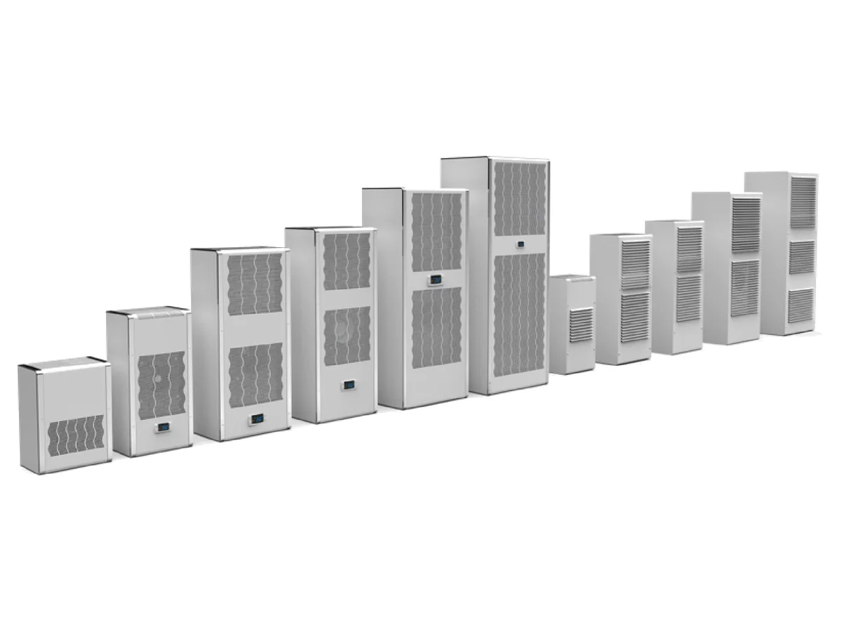
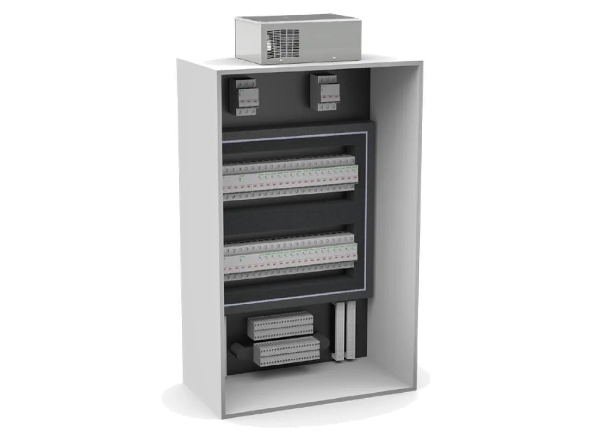
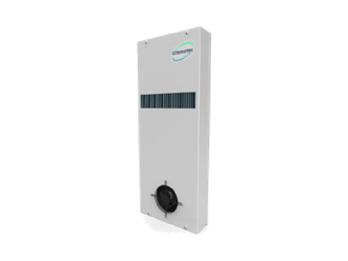
The cooling units come from Cosmotec (Protherm family, refrigerant R513A). The wall-mounted unit CVE is fitted to the side panel or to a sheet steel door. The roof-mounted unit ETE needs no space on the wall or door – useful in confined conditions, in rows of enclosures or where escape routes must stay clear. For enclosures outdoors there is the outdoor version CVO.
| Unit family | Mounting | Cooling capacity | Application |
|---|---|---|---|
| Cooling unit Protherm CVE | Side panel or door | 310–5,800 W | Interior: ambient warmer than permitted or high heat load |
| Roof-mounted cooling unit ETE | on the roof | 330–5.000 W | Interior, little space on wall and door, rows of enclosures |
| Cooling unit Protherm CVO | Side panel or door | 525–5.800 W | Enclosures outdoors |
| Air/air heat exchanger XVA | inside or outside the enclosure | 16, 35 or 50 W/K | Ambient cooler than inside, air dusty or oily |
Cooling capacity according to the Cosmotec catalogue, nominal value L35/L35 (35 °C inside and outside); at higher ambient temperature it is lower. Versions with 230 V and 400 V; ZPAS takes care of sizing and type selection.
Air/air heat exchanger
The heat exchanger separates internal and external air – two fans drive the air through separate ducts, dust, oil and moisture stay outside. Its output depends on the temperature difference:
Cooling capacity (W) = specific output (W/K) × (internal temperature − outside temperature)An XVA35 therefore delivers around 525 W at a 15 K difference. If it is warmer outside than inside, it does not cool – a cooling unit is then needed.
Filter fans and outlet filters
The filter fan draws ambient air in through the filter mat and pushes it into the enclosure; the outlet filter on the opposite side lets the warm air out. Fan at the bottom, outlet at the top – so the air flow supports natural convection. This works only as long as the ambient air is cooler than the permissible internal temperature. ZPAS uses filter fans of the LV series (Rübsamen & Herr) with matching outlet filter GV or equivalent, in 230 V or 115 V AC and 24 V DC.
Air flow (m³/h) = power loss (W) ÷ (0.34 × ΔT)| Type | Airflow with outlet filter | External dimensions | Outlet filter |
|---|---|---|---|
| LV 250 | 42 m³/h | 148 × 148 mm | GV 250 |
| LV 300 | 90 m³/h | 204 × 204 mm | GV 300 |
| LV 400 | 205 m³/h | 250 × 250 mm | GV 400/500 |
| LV 500 | 235 m³/h | 250 × 250 mm | GV 400/500 |
| LV 550 | 260 m³/h | 250 × 250 mm | GV 400/500 |
| LV 600 | 385 m³/h | 323 × 323 mm | GV 600/700 |
| LV 700 | 530 m³/h | 323 × 323 mm | GV 600/700 |
| LV 800 | 610 m³/h | 323 × 323 mm | GV 600/700 |
Values at 50 Hz with outlet filter according to the manufacturer's catalogue; free-blowing, the air flow is higher – the value with filter is what counts for sizing. Degree of protection IP 54 with filter mat; for outdoor use there is an IP 55 version (LV/GV 250–800 only) with finer Z-Line filter F5 and UV-resistant outer grille.
Heating and thermostat
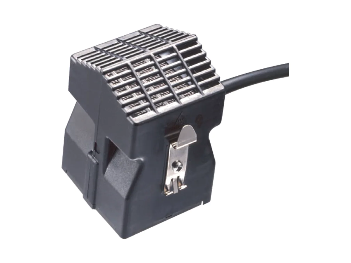
Against condensation and frost: the fan heater for the DIN rail (230 V, 200 or 400 W depending on connection, IP 20, 71 × 70 × 95 mm) and heating resistors from 30 to 600 W. Switching is done by thermostats with thermal bimetal, setting range 0–60 °C, switching differential approx. 7 K, switching capacity 10 A at 250 V AC (inductive 2 A) – as an NC contact (normally closed), which e.g. switches the heater off when the set temperature is exceeded, or as an NO contact (normally open), which e.g. switches the fan on.
| Component | Specifications | Catalogue number |
|---|---|---|
| Fan heater | 230 V AC, 200/400 W, fan 10 m³/h, IP 20, with DIN rail and holders | W-0316-09-00 |
| Thermostat NC | 0–60 °C, 10 A at 250 V AC, e.g. switches the heater off | W-0201-01-00-000-A |
| Thermostat NO | 0–60 °C, 10 A at 250 V AC, e.g. switches the fan on | W-0201-02-00-000-A |
Frequently asked questions — Electrical enclosure accessories
Do SZE2 accessories also fit the SZE3?
Partly. Identical are, among others, cable clamps, plinth corners, vibration dampers and plinth connection kit, roof and floor plates, 19″ profile rails, offset brackets and cross members, meter tray, power distribution panel, circuit diagram pocket and the vertical earthing bar. Specific to the series are doors, side panels, roofs, swing frames and the mounting rails: the SZE2 uses CLASSIC and UNI, the SZE3 uses mounting rails A, B and C for its 25 mm grid.
Is the accessory fitted at the factory?
Yes. In the electrical enclosure configurator you choose interior fittings, side panels, plinth and air conditioning directly; the enclosure arrives fitted from the factory, and on request also wired through panel building. Individual parts for retrofitting are ordered by catalogue number.
How much do the mounting plate, rail frame and swing frame carry?
For the SZE2 the catalogue gives 1,000 kg on the mounting plate, 1,600 kg on the mounting rail frame, 150 kg on the swing frame and 20 kg on the door. The SZE3 swing frame also carries 150 kg. On request ZPAS builds an SZE2 with a swing frame for 200 kg – with support roller and reinforced enclosure frame.
Does accessory change the degree of protection of the enclosure?
Yes, as soon as openings are created. With blanking covers the degree of protection is retained; perforated plates, filter mat, brush or foam pass-throughs in the roof or top cover reduce it to IP 00 to IP 21, depending on the version. Doors with passive ventilation and filter fans with filter mat have IP 54. The difference between IP 54 and IP 55 is explained in the IP guide.
Cooling unit, heat exchanger or filter fan – which do I need?
If the surroundings are cooler than the permissible internal temperature, filter fans (clean air) or an air/air heat exchanger (dusty or oily air) are sufficient. If it is warmer outside or the heat load is high, a cooling unit is needed. The cooling capacity calculator provides a guide value for your enclosure.
Order the accessories together with the enclosure?
Tell us the series, dimensions and the catalogue numbers you want – or describe your application and we will put the fit-out together. Quotation within 2 working days at most.